Current Applications of Brewster Angle Microscopy
Brewster angle microscopy
Reflection of light from surfaces is part of our daily experience. However, an amazing property of optics is the possibility of having zero reflection. In more detail no reflection occurs from a clean and perfect interface illuminated under a unique angle of incidence with p-polarized light. This well-understood phenomenon is described by Brewster ´ s law providing the so called Brewster’s angle for the involved optical media. Any subsequent changes of the optical properties at the interface will lead to reflection. This fact is the basis of Brewster angle microscopy, a recent technique for the study of nanofilms at the air/water interface or at the surface of other transparent nonadsorbing dielectric substrates (fig. 1).
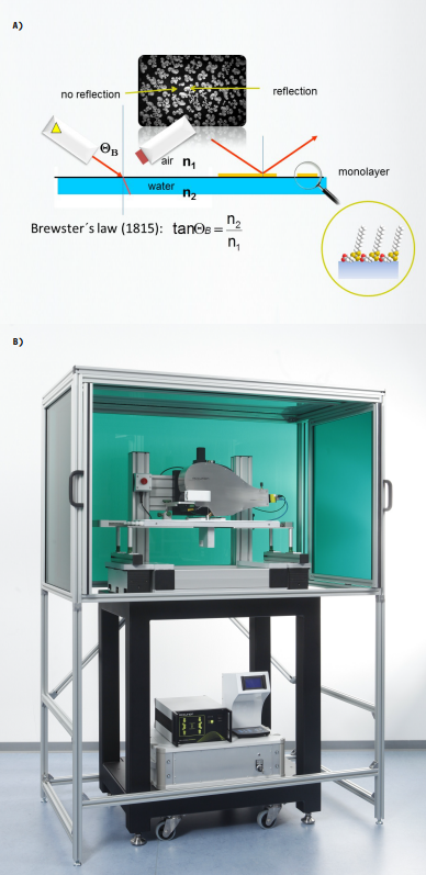
Figure 1: Brewster angle microscopy: Principals (A) and setup - nanofilm_ultrabam, Accurion GmbH, Göttingen (B).
Even just with a monolayer on an interface Brewster’s law is not fulfil led and the covered part of the surface reflects light although with very low in tensity. By increasing the intensity of the illumina tion the con trast between the covered and the clean part of the surface can be enhanced. By using a microscope op tic and a CCD-detector high contrast images of the lateral morpho logy of the layer can be taken.
The depth-of-focus problem
In Brewster angle microscopy the depth of focus problem is caused by the oblique imaging angle. With conventional optics, focus is achieved only in a narrow stripe. It is disturbing, especially at higher magnifications. A possible solution is a mechanical focus scanning in combination with image processing.
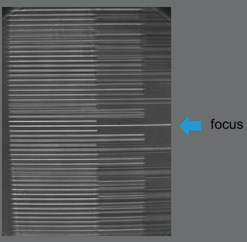
Figure 2: Depth of focus.
In the nanofilm_ultrabam a new optical approach is implemented. It allows high resolution and overall focused real-time Brewster angle microscopy.
1,2-Dimyristoyl-sn-glycero-3- phosphoethanolamin
In one of the papers introducing Brewster angle microscopy 1,2- Dimyristoyl-sn-glycero-3-phosphoethanolamin (DMPE) was used to illustrate the capability of the technique. To get an impression of the improvement to current ap plications, the same system is used.
Over all focused images were recorded (fig. 3) and the growth of a single Domain was followed (fig. 4A and 4B).
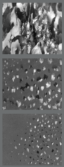
Figure 3: Monolayer of DMPE during firstorder phase transition, contrast in domains caused by long range orientation.

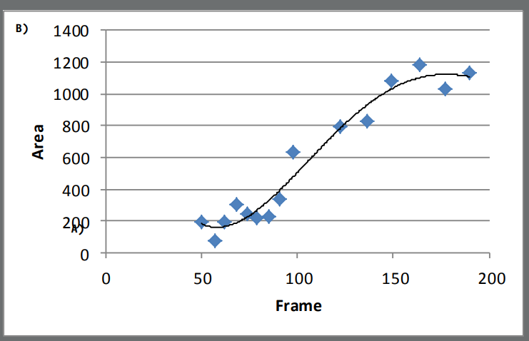
Figure 4: Growth of a single Domain: Trace (A), area/frame-diagram (B).
Ethyl-stearate
The condensed phase of ethyl stearate monolayers exhibits long range orientational order. The aliphatic chains are only weakly tilted in these monolayers. This has an effect on the textures of the monolayers. The nanofilm_ultrabam is equipped with a motorized analyzer to visualize optical anisotropy caused by long range molecular orientation order. To quantify the effect, the gray level distribution is displayed for a series of frames (fig. 5).
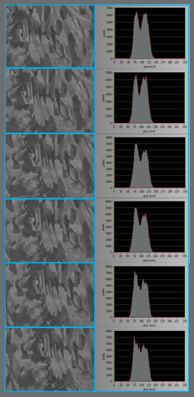
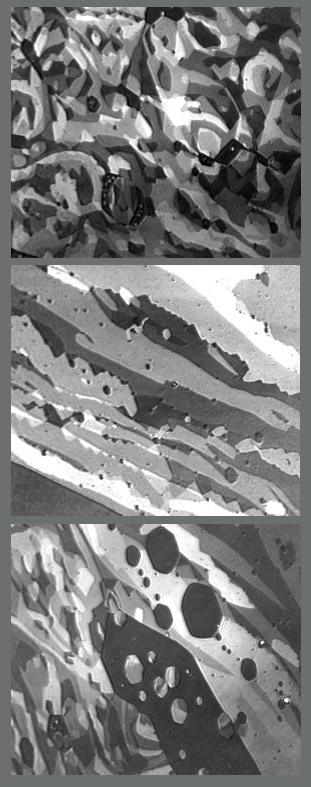
Figure 5: Ethyl-stearate Visualization of long range molecular orientation order: Brewster angle micrographs, gray level distribution
4-(Cyano-4[dodecylsulanylthiocarbonyl)sulfanyl] pentanoic acid Characteriasation of a Raft reagent at the air water interface.
Characteriasation of a Raft reagent at the air water interface.
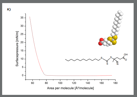

Figure 6: A-Isotherm (A), Brewster angle micrographs, gray leveland thickness distribution of the at 0.06 mN/m (B) 0.12 mN/m (expansion) (c) 3.4 mN/m (D)
